1 Suitable for fox hunts at 144mhz
2
Good screening
3 Attenuation selectable to suit S meter on radio
4
Easy to make with no special tools
5
Low cost approx £5.00 if parts have to be bought
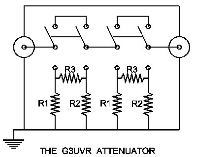
Construction
of Attenuator
|
1 Suitable for fox hunts at 144mhz 2
Good screening 3 Attenuation selectable to suit S meter on radio 4
Easy to make with no special tools 5
Low cost approx £5.00 if parts have to be bought |
|
One
of the most essential tools required to perform
I
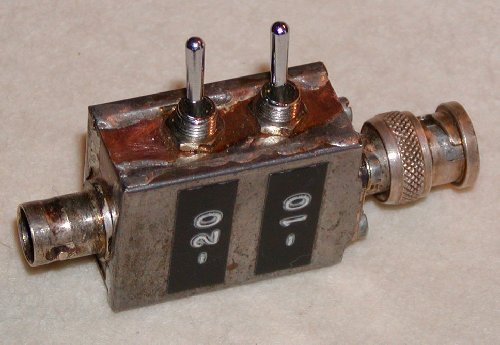
have now built three attenuators and have found a two-way PI-network unit to be
the most practical with 10db and 20db switched attenuation. This gives three
settings up to a maximum of 30db. Previous experiments suggest that greater
attenuation ahead of a handheld radio typically used on DF hunts the incoming
signal would bypass the attenuator anyway and get straight into the rig through
the plastic case. Pi-network configuration was chosen rather than T-network as
Pi gave a smaller neater unit with less lead lengths. The chosen attenuation
values where selected to give optimum performance with the dynamic range of the
LCD S meter in my Standard C500 handheld. I tried various values by
experimentation and found a value that when the S meter was just hitting
maximum, switching in the lowest value reduced the S reading just above minimum
so further peaking of the incoming signal could be done. This is what I refer to
as the dynamic range of the S meter. This arrangement gives four ranges of
hitting full scale on the S meter with just two switches!
Parts
required are a chassis BNC plug, chassis BNC socket, 2 DPDT (double pole double
throw) toggle switches and
6 resistors values selectable to suit the dynamic range of the S meter on your
radio. The box was made as small as possible out of double-sided PCB and an old
Duckhams oil can cut up and soldered to the PCB to complete the screening. The
overall size of the finished housing is unit is 37mm 27mm 17mm excluding sockets
and switches. This enables the input and output connectors to be directly
soldered to the switch poles and keeps all leads as short as possible. If a
chassis plug is used this means that you don't need a patch lead to connect it
to the rig. Connectors can be chosen to match the rig in use.
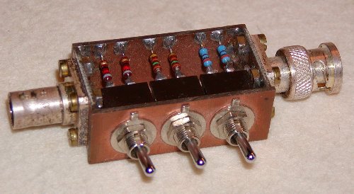
Cut
the top, bottom and ends out of double sided PCB and drill the holes for the
switches and sockets. Solder your
chosen R3 resistors and the shorting links on the back of the two switches and
fix to top PCB. The ends can now be soldered in place and the input output
connectors fitted and soldered. The bottom piece of PCB can now be soldered into
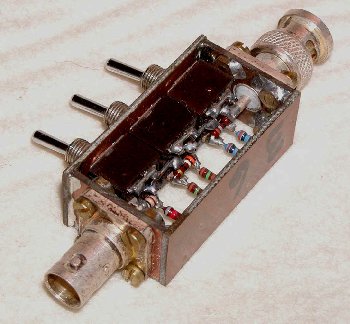
place and the R1 R2 resistors fitted as shown in the picture. The open three-way
attenuator shown in the photographs containing three, six and twelve db steps
was built for the purpose of varying the Tx RX drive to a transverter but other
wise is the same construction as my two-way DF unit. I used tin snips to cut up an
old oil can to make the side screens. After degreasing and when you are happy
with your chosen attenuation values solder the sides on to the PCB frame to
complete the screening.
Table of resistor values for Pi network 50ohm attenuator.
|
R1 R2
R3 3db
292 292
18 6db
150 150
37 10db
96 96
71 12db
84 84
93 15db
72 72
136 18db 64 64 195 20db 61 61 248 24db 57 57 395 |
|
Use
the nearest preferred values available e.g. in the case of 10db use 100 ohm
instead of 96 and 68 instead of 71. It does not matter that it ends up as 9.6db
and 51.9 ohms impedance.
Now
this construction page has been added to the clubs web-site it is
hoped that other members may upload articles about their home construction that
may be of interest to others locally or further a field.
In
a future article a "sniffer" will be described for use when within 100
meters of the fox.
My
thanks to Colin G3RLA who kindly took the photos
Denis
G3UVR
Return to Technical Articles Menu