Wirral & District Amateur Radio Club

Circuit Laws


George Simon Ohm (1787 to 1854) was a German physicist. Although he made considerable contributions to mathematics and acoustics, he is best remembered for his work relating to electrical resistance. The Ohm () is the SI unit of electrical resistance equal to that of a conductor in which a current of one AMP is produced by a potential of one Volt across it’s terminals.


Ohm’s law states that the direct electrical current flowing in a conductor is directly proportional to the potential difference between its ends. It states the relationship between voltage, current and resistance in a circuit and may be simply stated by the formula:


In a circuit incorporating resistive components only:

Note: RMS values of V & I must be used for alternating current circuits.

This can be combined with Ohm’s law to yield:

For an AC circuit containing non-resistive components:


Where PF is the Power Factor: the ratio between the real and apparent power in the circuit. For sinusoidal voltages and currents, the power factor is equal to the cosine of the phase angle between them. The power factor can be less than or equal to one.


Resistors in a series circuit are simply added together to find the total resistance. In other words, a 10 Ohm, 150 Ohm and 1000 Ohm resistor connected in series would be the equivalent of a single 1.160 Ohm resistor. The formula is:


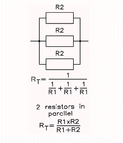
Resistors in a parallel circuit are a little more difficult. The formula to use is:

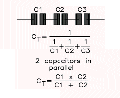
Capacitors behave exactly the opposite to resistors: when capacitors are in parallel, you add them:


Capacitors in series, on the other hand, are similar to resistors in parallel. You add the reciprocals:

Capacitors can pass alternating current (AC) signals while blocking direct current (DC) signals. They can also store electricity or act as filters to smooth out pulsating signals. Very small capacitors are usually used in high-frequency applications, such as radios, transmitters and oscillators. Very large capacitors normally store electricity or act as filters.


The unit of capacitance (electricity storage capacity) is expressed in farad, which is an extremely large amount of electricity and too large a unit to use in practice. Commonly used smaller units are the microfarad (abbreviated µF), nanofarad (nF) and picofarad (pF). The section on decimal multipliers shows the relationship between these. Some capacitance values are commonly expressed by only one unit while others can be expressed by two or more units, e.g. 1µF would rarely be called 1000nF and never 1,000,000pF, even though these are equivalent. However, 0.0047 µF is often expressed as 4.7nF, or as 4700pF. If the value contains a decimal point the µ, n or p is sometimes put in place of the decimal point. Therefore a 4.7pF capacitor can be marked as 4p7F. farad

   
Resistors               Capacitors

  Reproduced here by kind permission of Click for Maplin website

Return to 'How To' - Main Index